SPC Angle Tap IXPE Installation
GENERAL INFORMATION
Site Conditions and Installation
- For installations involving 3 season scenarios, meaning, the dwelling or installed space is without climate control for extended periods during certain seasons of the year, the post installation temperature range allowed is an ambient room temperature between -25°F and 155°F (-31.6°- 68.3°C). This allowance is for floating floors only and does not apply to glue-down installations.
-
Avoid exposure to direct sunlight for prolonged periods, doing so may result in discoloration. During peak sunlight hours, the use of drapes or blinds is recommended. Excess temperature due to direct sunlight can result in thermal expansion and UV fading.
-
Store cartons of tile or plank products flat and squarely on top of one another. Preferably, locate material in the center of the installation area (i.e. away from vents, direct sunlight, etc.)
Substrate Testing
NOTE: IT MAY NOT BE THE FLOOR COVERING INSTALLER'S RESPONSIBILITY TO CONDUCT THESE TESTS. IT IS, HOWEVER, THE FLOOR COVERING INSTALLER'S RESPONSIBILITY TO MAKE SURE THESE TESTS HAVE BEEN CONDUCTED, AND THAT THE RESULTS ARE ACCEPTABLE PRIOR TO INSTALLING THE FLOOR COVERING. WHEN MOISTURE TESTS ARE CONDUCTED, IT INDICATES THE CONDITIONS ONLY AT THE TIME OF THE TEST.
Concrete Subfloors
-
Do not install over concrete with a history of high moisture or hydrostatic conditions. Excessive moisture in the subfloor could promote mold, mildew, and other moisture related issues like the trapping of moisture emissions under the flooring, which may contribute to an unhealthy indoor environment. Shaw Industries does not warrant nor is responsible for damage to floor covering due to moisture related issues.
Wood Subfloors
APPROVED SUBSTRATES
Concrete Subfloors
NEW AND EXISTING CONCRETE SUBFLOORS SHOULD MEET THE GUIDELINES OF THE LATEST EDITION OF ACI 302 AND ASTM F 710, “STANDARD PRACTICE FOR PREPARING CONCRETE FLOORS TO RECEIVE RESILIENT FLOORING” AVAILABLE FROM THE AMERICAN SOCIETY FOR TESTING AND MATERIALS, 100 BARR HARBOR DRIVE, WEST CONSHOHOCKEN, PA 19428; 610‐832‐9585; HTTP://WWW.ASTM.ORG.
WARNING: DO NOT SAND, DRY SWEEP, DRY SCRAPE, DRILL, SAW, BEAD BLAST OR MECHANICALLY CHIP OR PULVERISE EXISTING RESILIENT FLOORING, BACKING, LINING FELT, ASPHALTIC “CUTBACK” ADHESIVES OR OTHER ADHESIVES.
These products may contain either asbestos fibers and/or crystalline silica. Avoid creating dust. Inhalation of such dust is a cancer and respiratory tract hazard. Smoking by individuals exposed to asbestos fibers greatly increases the risk of serious bodily harm. Unless positively certain that the product is a non‐ asbestos‐containing material, you must presume it contains asbestos. Regulations may require that the material be tested to determine asbestos content and may govern the removal and disposal of material. See current edition of the Resilient Floor Covering Institute (RFCI) publication Recommended Work Practices for Removal of Resilient Floor Coverings for detailed information and instructions on removing all resilient covering structures. For current information go to www.rfci.com.
Gypsum & Light Weight Concrete Subfloors
All recommendations and guarantees as to the suitability and performance of lightweight concrete under resilient flooring are the responsibility of the lightweight concrete manufacturer. The installer of the lightweight product may be required to be authorized or certified by the manufacturer. Correct on-site mixing ratios and properly functioning pumping equipment are critical. To ensure proper mixture, slump testing is recommended.
Wood Subfloors
Wood subfloors must be structurally sound and conform to guidelines of ASTM F 1482 and in compliance with local building codes.
-
Basements and crawl spaces must be dry. Use of a 6 mil black polyethylene is required to cover 100% of the crawl space earth. Crawl space clearance from ground to underside of joist is to be no less than 18” and perimeter vent spacing should be equal to 1.5% of the total square footage of the crawl space area to provide cross ventilation. Where necessary, local regulations prevail.
-
All other subfloors: Plywood, OSB, particleboard, chipboard, wafer board, etc. must be structurally sound and must be installed following their manufacturer’s recommendations.
-
Local building codes may only establish minimum requirements of the flooring system and may not provide adequate rigidity and support for proper installation and performance. If needed add an additional layer of APA rated underlayment, fasten and secure according to the underlayment manufacturer’s recommendations.
-
For Truss/Joist Spacing of More Than 16” up to 19.2” (488 mm) o/c: The standard is nominal ¾” (23/32”, 18.3 mm) T&G CD Exposure 1 plywood subfloor panels (Exposure 1) or nominal ¾” (23/32”, 18.3 mm) OSB Exposure 1 subfloor panels, 4’x8’ sheets, glued and mechanically fastened.
-
For Truss/Joist Systems Spaced Over 19.2” (488 mm) o/c up to a Maximum of 24” (610 mm): Minimum 7/8” T&G CD Exposure 1 plywood subfloor panels (Exposure 1) or minimum 7/8” OSB Exposure 1 subfloor panels, 4’x8’ sheets, glued and mechanically fastened. Alternatively, two layers of subflooring or bracing between the truss/joist in accordance with the truss/joist manufacturer’s recommendations and local building codes may be required. Note that some truss/joist systems cannot be cross-braced while maintaining stability.
Existing Floor Coverings
Flooring can be installed over most existing hard-surface floor coverings, provided that the existing floor surface is fully adhered, clean, flat dry structurally sound and free of deflection.
NOTE: THE RESPONSIBILITY OF DETERMINING IF THE EXISTING FLOORING IS SUITABLE TO BE INSTALLED OVER TOP OF WITH RESILIENT, RESTS SOLELY WITH INSTALLER/FLOORING CONTRACTOR ON SITE. IF THERE IS ANY DOUBT AS TO SUITABILITY, THE EXISTING FLOORING SHOULD BE REMOVED, OR AN ACCEPTABLE UNDERLAYMENT INSTALLED OVER IT. INSTALLATIONS OVER EXISTING RESILIENT MAY BE MORE SUSCEPTIBLE TO INDENTATION.
Quarry Tile, Terrazzo, Ceramic Tile, Poured Floors (Epoxy, Polymeric, Seamless):
-
Waxes, polishes, grease, grime, and oil must be removed.
-
Cuts, cracks, gouges, dents, and other irregularities in the existing floor covering must be repaired or replaced.
Raised Access Panel Subfloors
Radiant Heated Floors
The heating system's components must have a minimum of 1/2" separation from the flooring product. The system must be on and operational for at least 2 weeks prior to installation to reduce residual moisture. Three days prior to installation, lower the temperature to 65 degrees, after installation gradually increase the temperature in increments of 5° F to avoid overheating. The maximum operating temperature should never exceed 85°F. Use of an in-floor temperature sensor is recommended to avoid overheating. Contact the manufacturer of your radiant heating system for further recommendations.
-
Electric Radiant Floors: consist of electric cables (or) mats of electrically conductive materials mounted on the subfloor below the floor covering. Mesh systems are typically embedded in thin-set. When embedding the system components, use cementitious patching and leveling compounds that meet or exceed Shaw’s maximum moisture level and pH requirements. Use of gypsum-based patching and/or leveling compounds which contain Portland or high alumina cement and meet or exceed the compressive strength of 3,000 psi are acceptable.
SUBSTRATE PREPARATION
Concrete Subfloors: New and existing concrete subfloors should meet the guidelines of the latest edition of ACI 302 and ASTM F710, “Standard Practice for Preparing Concrete Floors to Receive Resilient Flooring” available from the American Society for Testing and Materials, 100 Harbor Drive, West Conshohocken, PA 19428; 610-832-9585: HTTP://WWW.ASTM.ORG.
Wood Subfloors: Wood subfloors must be structurally sound and conform to guidelines of ASTM F 1482 and in compliance with local building codes.
-
All substrates must be structurally sound, clean, dry, and flat prior to installation. Surfaces must be free of contaminants including, but not limited to: dust, dirt, oil, grease, paint, curing compounds, concrete sealers, adhesive residues, loosely bonded toppings, and any other materials or conditions that may inhibit proper adhesion.
-
Fill depressions or cracks with a cementitious patching / leveling compound that meet or exceed Shaw Industries maximum moisture level and pH requirements. Use of gypsum-based patching and/or leveling compounds which contain Portland or high alumina cement and meet or exceed the compressive strength of 3,000 psi (20684 kPa) are acceptable.
-
Dormant cracks wider than 1/32” (0.8 mm) may be repaired using Prepworx CJR400.
-
For cracks and saw cuts exceeding 1” (25.4 mm) in depth, the use of Prepworx MRS101 is recommended.
-
Moisture Mitigation: For new or existing concrete substrates exhibiting moisture levels that exceed the limits specified for products and/or adhesives, the use of Prepworx VBS311 is recommended.
-
Do not install flooring over substrates that have been chemically abated: Chemically treated surfaces may compromise adhesion and affect flooring performance.
-
Curing compounds: (DO NOT USE). If present, they can interfere with the bond of the adhesive to the concrete. Seek assistance from the substrate manufacturer if curing agents are detected.
-
Sweeping Compounds: Green sweeping compounds can be used but must be swept and removed immediately.
-
For dusting / powdering / porous concrete / lightweight concrete prime with a latex primer such as 9050.
ADHESIVE AND APPLICATION
NOTE: Secondary method of installation approved for glue down only
Adhesives provide variations of shear and peel strength depending on chemistry and application. The use of a proper adhesive is important for installation as the adhesive provides the bond of the flooring to the substrate to restrict movement. It is important to understand the site conditions and installation in choosing the correct adhesive for the installation.
Glue Down Installation: SPC products are approved for glue down installation over approved wood and concrete substrates. Follow adhesive label application instructions. Install flooring into wet adhesive to achieve a permanent bond. Maintain 1/4” (6.35 mm) perimeter expansion space. Refer to adhesive label for moisture limits of the adhesive. Roll flooring immediately after installation with a 100 lbs. 3‐section roller.
-
Recommended Adhesive(s): LokWorx 200, Kwik Flash, T-180 or comparable adhesive. If alternative adhesives are used, a bond test should be performed to ensure compatibility.
|
Adhesive
|
Type
|
CaCl/MVER Limit
|
RH Limit
|
PH Limit
|
Open Time
|
Working Time
|
Trowel Size
|
|
200
|
TPS
|
12 lbs
|
99%
|
5-12
|
10-30 minutes
|
1hour
|
1/16”x1/16”x1/16” sq. notch
|
|
Kwik Flash
|
HS
|
n/a
|
99%
|
7-12
|
10-30 minute
|
1 Hour
|
1/16”x1/16”x1/16” sq. notch
|
|
T-180
|
HS
|
N/A
|
95%
|
7-10
|
10-30 minutes
|
1 hour
|
1/16”x1/16”x1/16” sq. notch
|
INSTALLATION
Tools: Tape Measure, Utility Knife, Jigsaw, Tapping Block, Rubber Mallet/Dead Blow Mallet, Pull Bar, ¼" Spacers, T-Square, Safety Glasses, Broom or Vacuum and, if necessary, tools for subfloor repair.
FLOATING INSTALLATION: SPC flooring is designed to be installed utilizing the floating method. Proper expansion space 1/4” (6.35 mm) is required. Undercut all doorjambs. Do not fasten wall moldings and or transition strips to the flooring.
GLUE DOWN INSTALLATION: SPC products are approved for glue down installation over approved wood and concrete substrates. Follow adhesive label application instructions. Install flooring into wet adhesive to achieve a permanent bond. Maintain 1/4” (6.35 mm) perimeter expansion space. Refer to adhesive label for moisture limits of the adhesive. Roll flooring immediately after installation with a 100 lb. 3‐section roller.
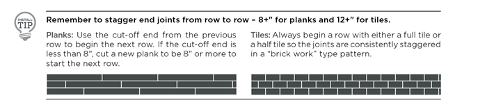
Flooring must be installed in a staggered (offset) pattern.
PRIMARY INSTALL METHOD
.jpg?width=200&height=90 "Timberidge_Step1_Tools-(1).jpg")
1. Gather your tools |
.jpg?width=200&height=90 "Timberidge_Step-2_Clean-(1).jpg")
2. Make sure your space is: clean, flat, dry and structurally sound. |
.jpg?width=200&height=90 "Timberidge_Step-3_MeasureSpace-(1).jpg")
3. Measure your space |
.jpg?width=200&height=90 "Timberidge_Step-4_StartWall-(1).jpg")
4. Choose your starting wall |
.jpg?width=200&height=90 "Timberidge_Step-5_StartCorner-(1).jpg")
5. Place tongue side in the starting corner (work from left to right). |
.jpg?width=200&height=90 "Timberidge_Step-6_Spacers-(1).jpg")
6. Use several spacers to maintain 1/4"expansion gap along the walls. |
.jpg?width=200&height=90 "Timberidge_Step-7_LockEnds-(1).jpg")
7. Lock the short ends together to complete your first row. Cut the planks as needed to fit the space. |
.jpg?width=200&height=90 "Timberidge_Step-8_StartSecRow-(1).jpg")
8. Start your second row. With a cut-off that is more than 8" long or start with a new plank. |
.jpg?width=200&height=90 "Timberidge_Step-10_SecondPlank-(1).jpg") 9. Connect the length side at a slight angle, engage the long side and rotate down. 9. Connect the length side at a slight angle, engage the long side and rotate down. |
.jpg?width=200&height=90 "Timberidge_Step9_RotateDown-(1).jpg") 10. Continue installing the row 10. Continue installing the row
|
.jpg?width=200&height=90 "Timberidge_Step11_Repeattofinish-(1).jpg")
11. Repeat steps to finish the room |
|
-
Plan the Layout: Before beginning installation, carefully plan the layout of the flooring. Proper planning helps avoid narrow plank widths at wall edges and very short pieces at the ends of rows.
-
Prepare the Starter Row: Determine whether the first row of planks needs to be trimmed. If not, remove the unsupported tongue to ensure a clean, solid edge faces the wall.
-
Begin Installation from the Left: Start installing from the left side of the room, working toward the right while facing the starting wall or standing in front of the planks.
-
Install the First Row:
-
Install the Second Row:
-
For the next plank, insert the short end tongue into the groove of the previous plank. Align the long side tongue just above the groove lip of the first-row plank, then angle and lock it into place with minimal force.
-
Continue Row by Row: Work across the room, completing the first and second rows. These rows form the foundation of the installation, so ensure they are straight and square. Check alignment frequently.
-
Cut and Fit the Last Plank in the Row: Cut the final plank in the first row to fit, leaving a ¼" (6.35 mm) expansion gap. Use the “score and snap” method with a utility knife. If the leftover piece is at least 8" (20.32 cm), use it to start the third row.
-
Maintain a Random Pattern: Continue installing planks, ensuring a random pattern with end pieces no shorter than 8" (20.32 cm). Confirm that all planks are fully engaged. If gaps appear, use a tapping block and a scrap piece of flooring to gently close them without damaging the planks.
-
Fit Under Door Casings: The locking system’s flexibility allows for easier fitting under door frames. Use a flat pull bar if needed to lock planks in tight spaces.
-
Cut Around Obstacles: For irregular areas or obstacles, use a jigsaw or rotary tool to cut planks. Creating a cardboard template of the area can help ensure accurate cuts.
SECONDARY INSTALL METHOD
NOTE: Secondary method of installation approved for glue down only.

Step 1: Gather your tools |

Step 2: Make sure your space is: clean, flat, dry and structurally sound. |

Step 3: Begin installation working from left to right. Insert spacers at ends and edges where tiles meet wall to maintain ¼” expansion space |

Step 4: Lock short end of tile by inserting tongue into groove at an angle and drop in place. Continue to end of first row. |

Step 5: Use leftover tile from first row as starter for second row. Minimum 8” stagger between tile end joints. |

Step 6: Lock long edge of tile by inserting tongue into groove at an angle and drop in place. Slide tile toward end of previously installed tile until the tongue just touches the groove. |

Step 7: Use hammer and tapping block to engage tile and ensure tight fit. |

Step 8: Attach a scrap piece to align tiles and bridge gaps between tile. |

Step 9: Tap end of tiles with hammer and tapping block to engage ends. |

Step 10: Use hammer and pull bar to engage final piece, insert spacers and continue to next row. |

Step 11: Use hammer and pull bar to lock tiles on final row. |
|
COMPLETION
-
Adhering tape to the surface of your resilient flooring could damage the surface.
Do not use tape to secure floor protection directly to the floor during construction or renovation. Instead, adhere tape to the material used to protect the floor and secure it to the base molding along the wall. A material such as ram board can also be used to protect your flooring.